A point cloud is one of the most information-rich datasets you can bring to a construction or renovation project.
Millions of verified spatial measurements, captured in hours, reflecting exactly what exists on site. But raw scan data isn’t a usable deliverable on its own. It needs to become a model. And for most Australian architecture, engineering, and construction teams, that means point cloud to Revit.
This guide walks through the complete workflow, common pitfalls, and the decisions that determine whether a Revit model from a point cloud project delivers a model you can actually build from.
Why Revit?
Revit is the industry-standard BIM authoring tool for building and infrastructure projects in Australia.
When point cloud data is converted into a Revit model, it becomes an intelligent, parametric asset. Walls carry material data, structural elements have load properties, MEP systems are routable and schedulable. The model can support design coordination, clash detection, quantity take-offs, and facility management.
The alternative produces geometry without intelligence. For any project requiring BIM drawing services or downstream coordination, Revit is the right destination for your scan data.
The Point Cloud to Revit Workflow
Step 1: Site Scanning
Everything downstream depends on the quality of the scan. A LiDAR scanner is set up at multiple positions throughout the site, capturing interior and exterior geometry, structural elements, MEP services, and architectural features. For a typical commercial building, scanning takes one to two days on site.
The scanner captures data to ±1–3mm accuracy: a baseline that Revit modelling from point cloud work depends on. If the scan is patchy, misregistered, or taken with the wrong equipment for the project scope, no amount of modelling skill compensates for the gaps.
For a detailed breakdown of what the laser scan-to-model process involves from capture through to deliverable, Avian’s scan-to-model guide covers the full picture.
Step 2: Point Cloud Registration and Processing
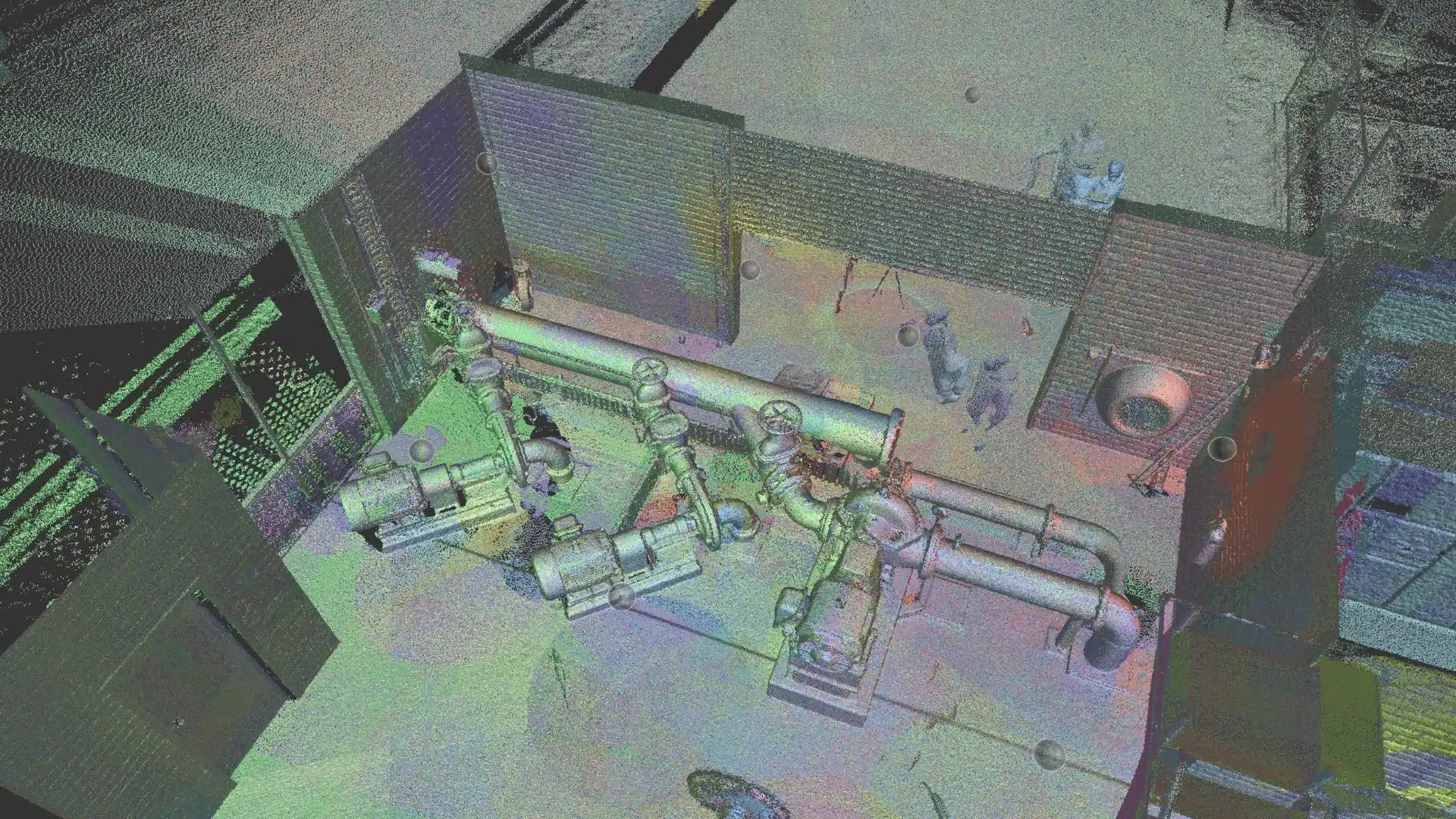
Raw scan files from each scanner position are registered and aligned into a single unified coordinate system using common reference points (targets or natural features). The result is a single, clean point cloud covering the entire site.
This stage also involves noise removal, filtering out moving objects captured during scanning (people, vehicles), scanner artefacts, and data outside the project boundary. A registered, cleaned point cloud is the actual starting point for modelling.
File formats matter here. Revit natively supports RCP/RCS files (Autodesk’s recap format). Raw scan files from common scanners (e.g. Leica, FARO, Trimble) need to be processed into RCP before import. E57 is a common interchange format used when handing point clouds to third-party modellers.
Step 3: Linking the Point Cloud in Revit
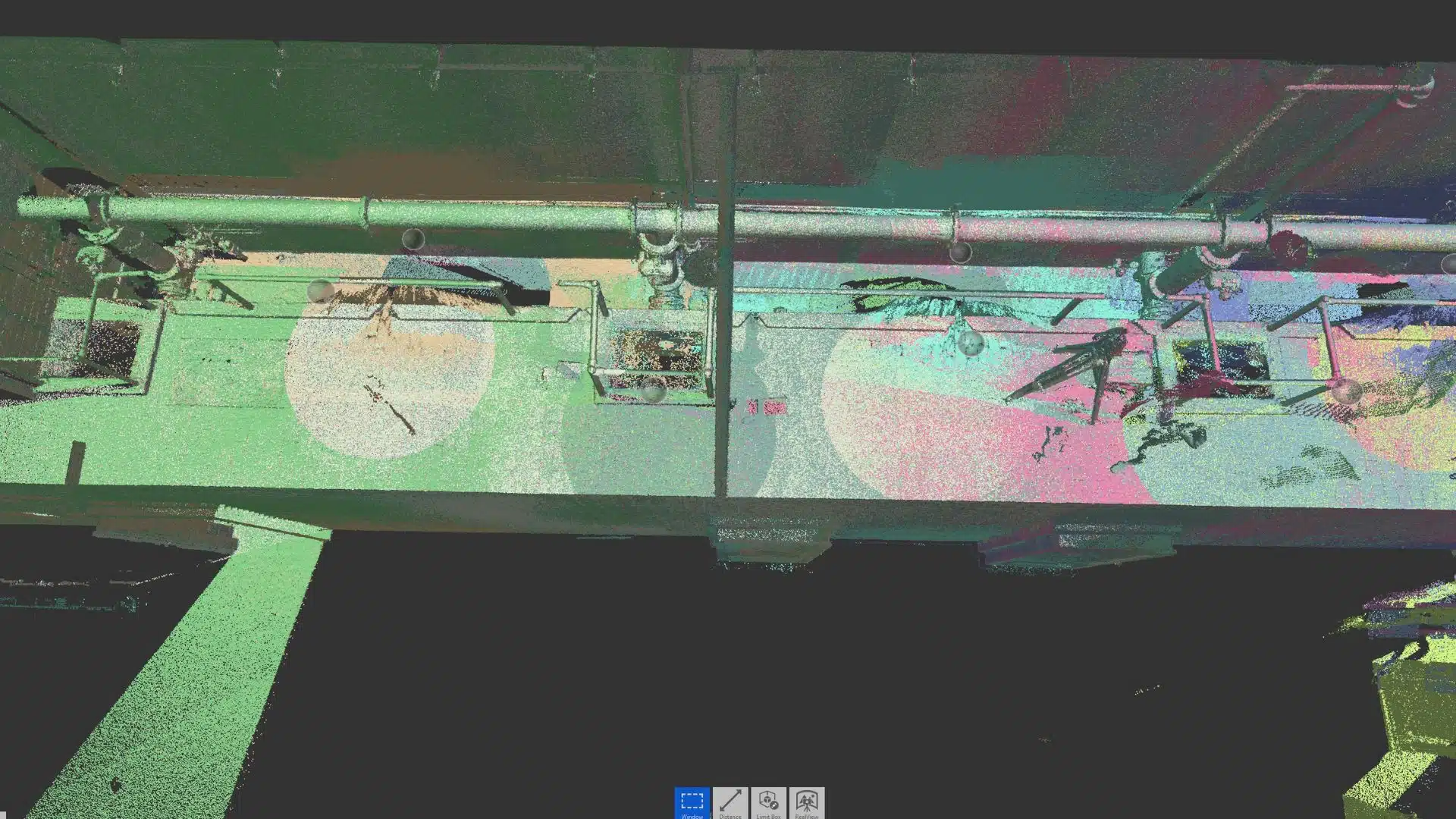
The processed point cloud is linked into Revit via the Insert > Link Point Cloud function. The cloud appears as a visual reference overlaid on the Revit model environment. Density display settings (max points, level of detail) are adjusted based on hardware capability. Point clouds are large datasets, and unoptimised display settings will slow the model significantly.
A critical early decision: coordinate system alignment. The point cloud should be linked using Shared Coordinates, not Project North, so the model sits correctly in real-world space. Getting this wrong at Step 3 causes compounding errors across every subsequent view and sheet.
Step 4: Modelling Disciplines Against the Cloud
With the point cloud linked, modelling begins. The approach depends on the project scope and the required Level of Development (LOD):
Architectural elements
Walls, floors, ceilings, roofs, and openings are typically modelled first. Walls are placed to match the point cloud geometry, with thickness and layer composition assigned per the project specification. Openings are located from the scan data rather than assumed.
Structural elements
Columns, beams, slabs, and cores are modelled to match the scan, including any deviations from nominal (a column that’s slightly out of plumb, a beam with visible deflection). This is where scan-based modelling is most valuable over drawing-based modelling. The geometry is what actually exists, not what was specified.
MEP systems
Ductwork, pipework, cable trays, and equipment are modelled last in most workflows, as they occupy the tightest tolerances. Accurate MEP modelling from scan data is essential for architectural workflows with point cloud data involving fitout, refurbishment, or services coordination.
For infrastructure and civil applications, point cloud data supports road geometry, bridge structures, and utility corridor documentation. Avian’s guide on point cloud uses in infrastructure covers these workflows in more detail.
Step 5: Quality Checking Against the Point Cloud
Before a point cloud to Revit model is issued, it needs to be checked against the source data, not just visually, but systematically.
Modellers should review section cuts, plan views, and elevations against the cloud to verify that modelled elements align with scan geometry within the project tolerance (typically ±5–10mm for building elements at LOD 300).
Common issues at this stage include walls that don’t match the scan profile due to surface irregularities, column centrelines offset from the scan geometry, and floor levels that don’t account for actual slab variation.
Step 6: Delivery and Coordination
The completed Revit model is issued in RVT format, with IFC available for open-format workflows. Navisworks NWC export enables coordination and clash detection. Sheet sets, schedules, and views are configured to project requirements.
Common Mistakes in Revit Modelling from Point Cloud
Importing without registration
A point cloud where individual scan positions aren’t properly registered will show seams, offsets, and geometry that doesn’t align. Always confirm registration accuracy before modelling begins.
Ignoring real-world deviations
The point cloud shows the building as it actually is, including the column that’s 18mm off grid, the floor that dips 30mm across the plate, the wall that’s not quite plumb. Models that force nominal geometry over scan reality undermine the entire purpose of scan-based modelling.
Setting LOD too high for the brief
Full MEP routing at LOD 400 on a building that only needs LOD 300 coordination models wastes significant time and budget. Agree on LOD requirements per element before modelling starts.

Working with Avian
Avian handles the complete point cloud to Revit workflow in-house – from laser scanning across Melbourne, Sydney, and Brisbane – through to registered point clouds and fully coordinated Revit models delivered to your LOD specification.
Working with a single team across scanning and modelling removes the handover risks that arise when raw scan data is passed between providers. The people who captured the data are the same people who model from it.
Ready to start? Contact Avian today on 1300 081 115.